Workflow Editor
The Workflow Editor lets you create visual automation workflows that automatically update building states based on sensor inputs and conditions.
Overview
Workflows connect inputs (sensor data, building states) to outputs (building state changes, traffic control) through logic operators.
Example workflow:
"If Database AND API Server are both offline, set the Status Dashboard to critical"
Interface Layout
The Workflow Editor has three panels:
- Left Panel - Assets and Operators palette
- Center - Canvas for building workflows
- Right Panel - Saved workflows list
Left Panel - Assets
City Layout Selector
Select which layout's buildings to use in the workflow.
Groups
Buildings are organized by their groups (as defined in Control Center):
- app-deco - Application decoration buildings
- db-deco - Database buildings
- front-deco - Frontend buildings
Click a group to expand and see its buildings.
Asset List
Each asset shows: - Building type icon - Asset name - Count of instances
Drag assets from this list onto the canvas to create input nodes.
Left Panel - Operators
Logic Operators
| Operator | Symbol | Description |
|---|---|---|
| AND | & | Both inputs must be true |
| OR | | | At least one input must be true |
| NOT | ! | Inverts the input (true→false) |
| EQUALS | = | Compare two values |
Actions
| Action | Description |
|---|---|
| SET STATUS | Change an asset's status |
| SET GROUP | Set status for all group members |
| SET TRAFFIC | Control traffic density/speed |
| SET CAMERA | Control camera path playback |
Center Canvas
Canvas Controls
- Zoom +/- - Adjust zoom level
- Reset View - Center and reset zoom
- Clear All - Remove all nodes from canvas
- Workflow name - Input field at the top
Creating Nodes
- Drag an asset or operator from the left panel
- Drop it on the canvas
- The node appears ready for configuration
Node Types
Input Nodes (Blue)
Created from assets. Configure: - Status equals: Value to match (offline, online, warning, critical)
Example: db0 checks if the building's status equals "offline"
Logic Nodes (Orange)
Created from logic operators. Connect multiple inputs: - AND: All inputs must be true - OR: Any input can be true - NOT: Single input, inverts result - EQUALS: Compare two values
Output Nodes (Pink/Red)
Created from action operators. Configure: - Target Asset: Which building to modify - Set to: New status value - Latch: Lock output (see below)
Connecting Nodes
- Click on a node's output socket (right side)
- Drag to another node's input socket (left side)
- A connection line appears
Deleting Connections
Click on a connection line to select it, then press Delete.
Deleting Nodes
Click on a node to select it, then click the X button or press Delete.
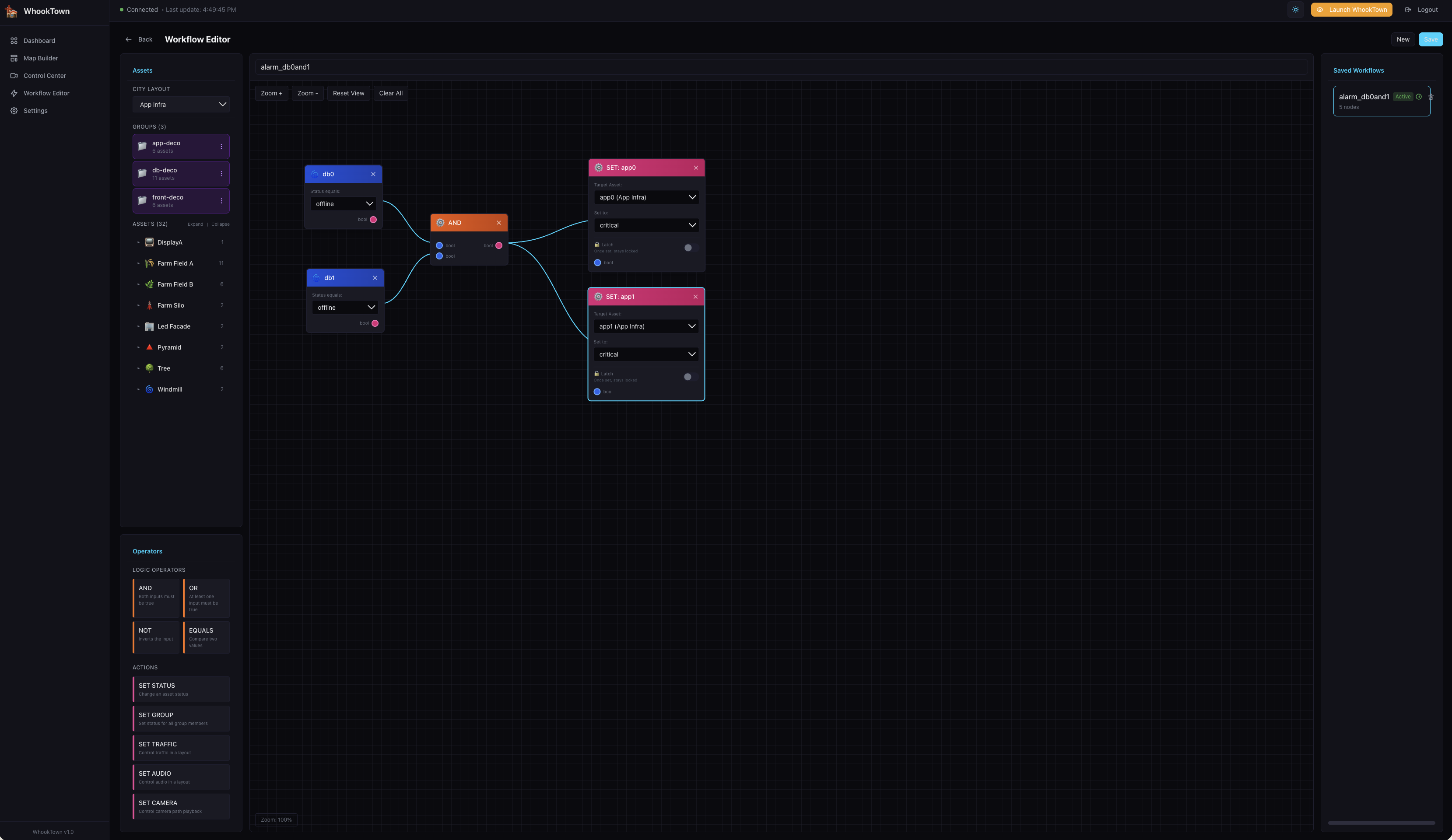
Example Workflow
This workflow demonstrates:
- db0 (input) - Checks if db0 status equals "offline"
- db1 (input) - Checks if db1 status equals "offline"
- AND (logic) - Both must be true
- SET: app0 (output) - Sets app0 to "critical"
- SET: app1 (output) - Sets app1 to "critical"
Result: If both databases are offline, both app servers show critical.
Latch Feature
The Latch option on output nodes locks the output value:
- When triggered, the output stays at that value
- Even if conditions become false, it remains latched
- Manual reset (changing status via Control Center) clears the latch
- Useful for "alert once and hold" scenarios
Latch Configuration
- Latch checkbox - Enable latching
- Latch Value - Value that triggers latch (default: any non-online status)
Right Panel - Saved Workflows
Workflow List
Shows all saved workflows: - Workflow name - Active badge (if enabled) - Enable/disable toggle - Delete button
Creating a New Workflow
- Click New button in header
- Build your workflow on canvas
- Enter a name
- Click Save
Editing a Workflow
- Click on a workflow in the list
- It loads into the canvas
- Make changes
- Click Save
Enabling/Disabling
Toggle the switch next to a workflow to enable or disable it. Disabled workflows don't process inputs.
Workflow Execution
When Workflows Run
Workflows execute when: - Sensor data is received - Building state changes - Workflow is enabled
Execution Order
- Inputs evaluate current building states
- Logic operators process conditions
- Outputs apply state changes if conditions are met
- Changes broadcast to all connected clients
Multiple Workflows
You can have multiple active workflows. They execute independently and can affect the same buildings.
Circular dependencies
Avoid creating workflows that trigger each other infinitely. The system has protection, but it's best to design carefully.